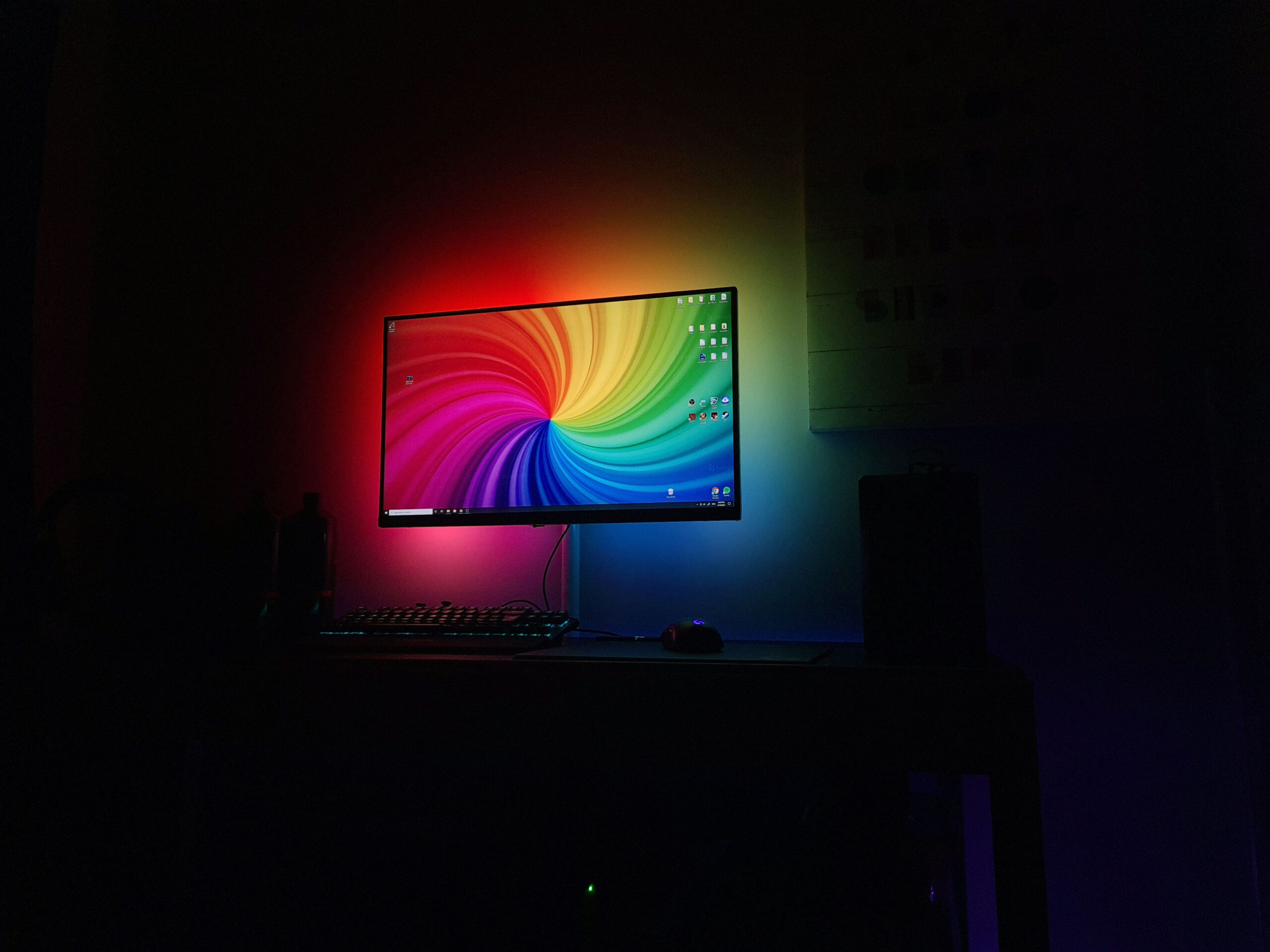
You’ve seen that fancy lighting system from a certain major highstreet brand. That’s right – Phillips Ambilight. It’s an expensive technology that is integrated into many of its top of the line televisions. It’s beautiful, much like its Hue range, but if you’re like me and struggling financially through lockdown, you can easily do it yourself on the cheap.
Do you want to find out how to create your own PC Ambilight setup? Well, today, I am going to show you how you can achieve the same effect with nothing more than an Arduino, A Strip of LED lights, Software trickery and a little bit of patience.
Save yourself money
Ambilight (or any quality lighting) is great for reducing eye strain. Not only that, but it looks awesome as well. Phillip’s Ambilight is generally reserved for their higher-end OLED ranging anywhere from $800 upwards – that’s no small coin. For a fraction of the cost, you can get this technology behind your monitor for less than $100.
How do I create my own Ambilight setup for my gaming PC?
I should say that this guide on how to create an Ambilight setup for your gaming PC will not work on a TV. This method sends wireless signals processed by software installed on your computer and therefore handles all of the video processing. If you want to create your own Ambilight setup for your TV, you will need a RasberryPi and HDMI capture which I will cover in a later article.
We will use a modified version of a program called Prismatik to capture our screen and figure out the colours around the edge of our pc monitor while simultaneously sending via the WiFi to our Arduino, which is connected to LED Strips.
Prismatik handles all of the heavy-lifting by processing all the video and generating the right code for WLED to interpret. The software also comes with some mapping and optimisation functionality, which will let you precisely position our LED strips, control gamma levels, and send accurate data to our Arduino.
DIY Ambilight Hardware Required
I recently reviewed the led strips we will be using today and was really impressed, which is why I ordered some more and did this project. The colours are accurate, and the hues are nice for setting some ambience.
If you have some WS2812B led strips laying around, those will do too.
| Item | Description | |
|---|---|---|
| 5 meter SK6812/WS2812 – 60 led per meter | WS2812B and SK6812 are addressable RBG strips. The only difference between the two is the SK6812 comes with a separate white diode allowing us to achieve better hues and more pastel shades without seeming too bright. | Link |
| Wemos D1 Mini ESP8266 | ESP8266 based Arduino development board. It comes with onboard USB and wireless and saves us having to solder these components separately. | Link |
| 20awg LED Wire | Some quality 20AWG Led wire will save you a lot of headaches down the line as you gain confidence setting up, inevitably you are going to start using longer lengths. | Link |
| 1000uf Capacitor | It’s recommended to bridge the 5v input terminals to protect the leds and arduino against power spikes when the power source is first turned on | Link |
| Breadboard | A breadboard is generally used for prototyping however, I’m still using mine to power my lights. Its handy to have one just in case, it makes the initial setup and testing really easy. | Link |
| Breadboard Wires | While you will only need to use one or two, you can never have enough of them around. | Link |
| 5v power supply | Amperage will be determined by how many LEDs you wish to run, the formula for figuring this out is below. | Link |
| Soldering Iron | You will need an adjustable soldering iron capable of soldering around 400f. I have linked the exact kit I am currently using and it’s serving great for hobbyist soldering. | Link |
Software Required
You might also like


| WLED |
Prismatik
Wiring Schematic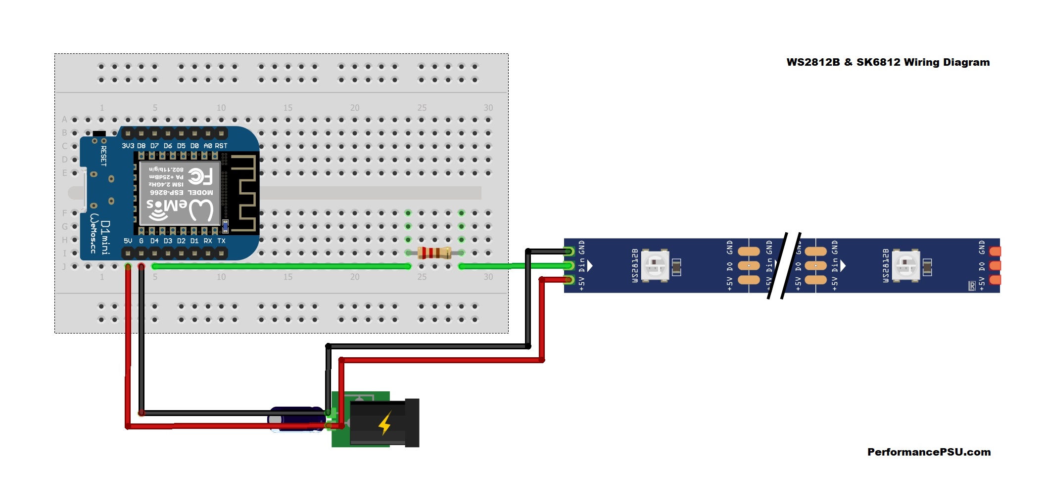
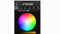
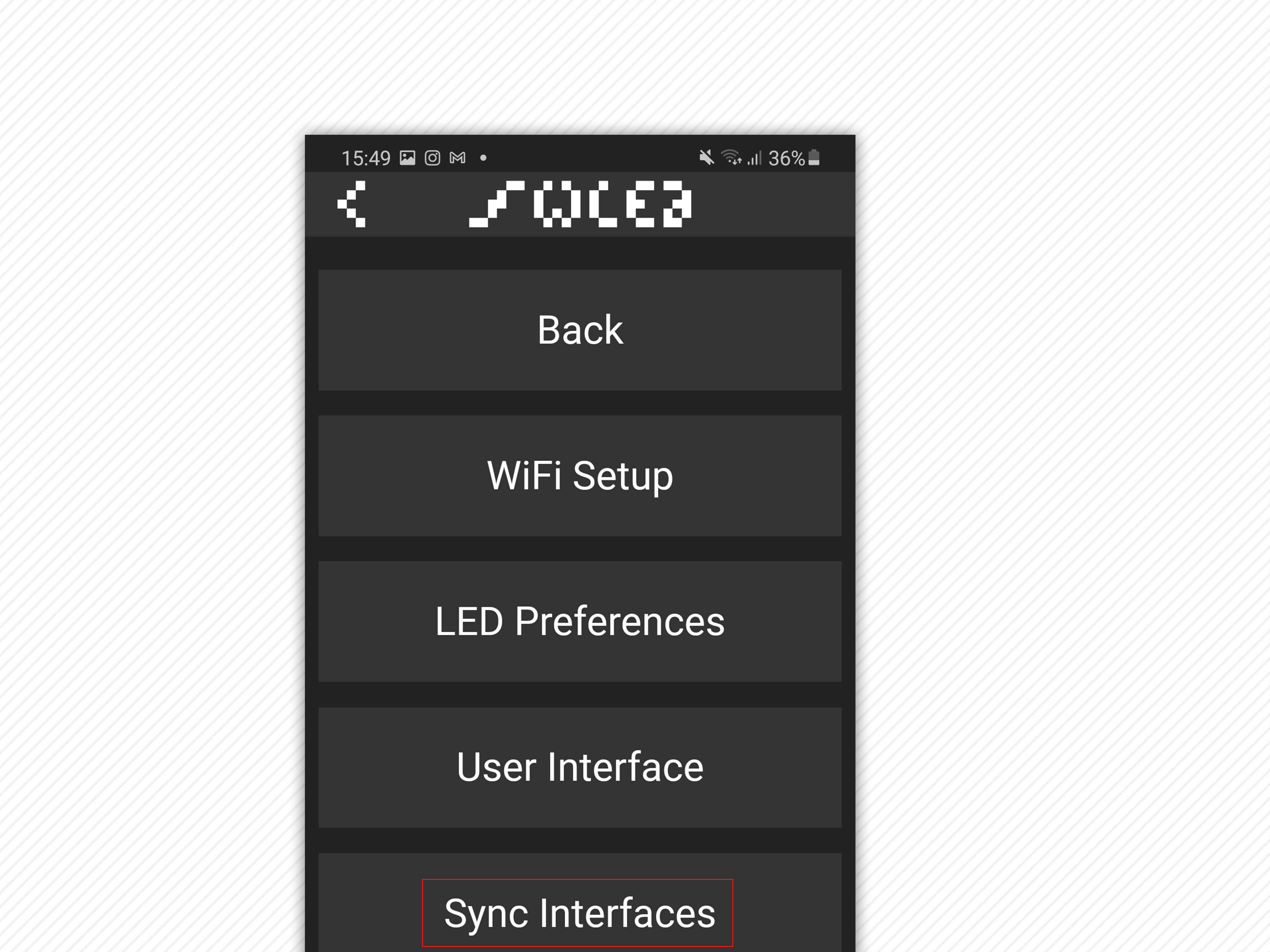
We recently did an article that showed you how to create your own RBG lighting setup using this exact same setup. If you have not seen it already, you should check it out. There is a host of useful information, including how to solder the pins on to your Arduino, schematics, and helpful videos. Step by Step PC Ambilight GuideInstall WLED on your Arduino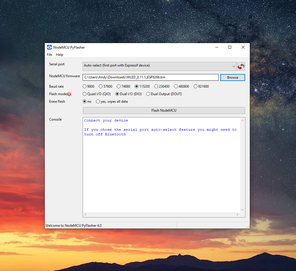 Our do-it-yourself Ambilight setup will use the same hardware and software as we used in our earlier guide. Follow the link below and follow the guide to install WLED on your Arduino in preparation for the rest of the guide, which we will complete here. How to install WLED on an Arduino using Pyflasher Configure WLED to accept UDP connectionsSo I assume you have installed WLED already and have it connected to your WiFi and the mobile app installed on your phone? Good job! The things you can do out of the box are amazing. If you opted for the SK6812, you’re in for a treat. To configure WLED to accept incoming data, you will need to open the mobile app and go to 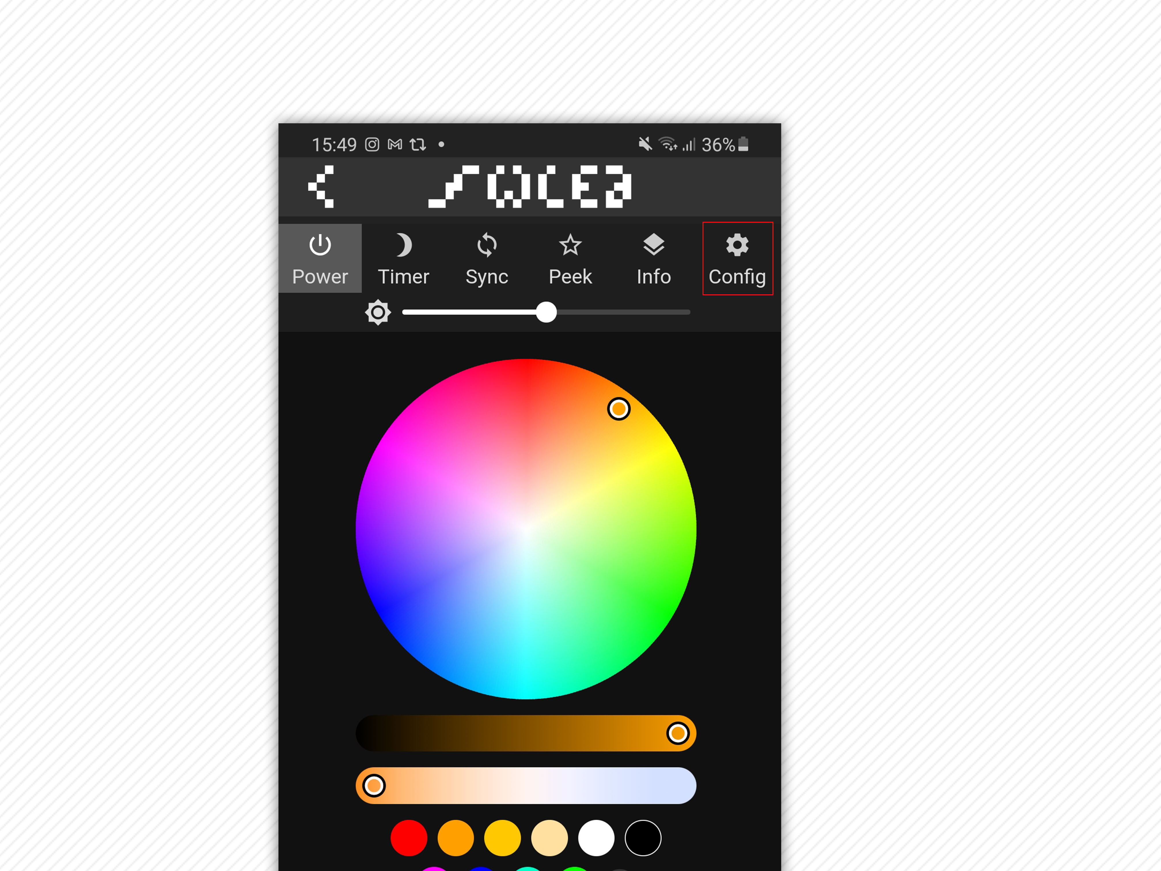
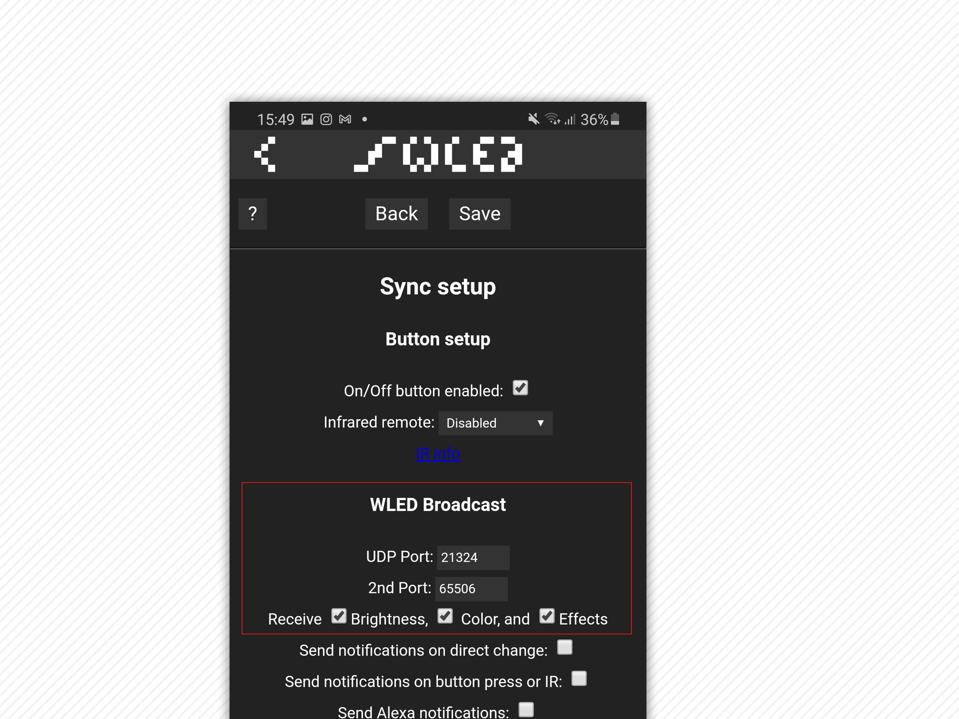
You will need to make sure UDP receive is on for Brightness, Color and Effects. Install Prismatik & ConfigurePrismatik is a part of the Lightpack ecosystem. It can be downloaded at the following link: https://github.com/psieg/Lightpack/releases We are not using the official release of Lightpack Prismatik as it is rarely maintained. The above repo is actively maintained and comes with some nice optimisations such as better DirectX grabbing and UDP support for WLED. Once you have downloaded the Software, you need to enable a few settings first to get the most out of the software; Complete each step in order, and you will come out of the other side with Ambilight enabled, and data is streamed wirelessly. The video above will show you the steps to configure Prismatik correctly; otherwise, the steps below will do the same as well.
ConclusionIf you followed all the steps above, you should have everything working; if not, then leave a comment, and I’ll get you on the right track. |
|---|